
Force directed graphs in D3
A force layout does not place nodes; it simulates them, and the picture settles once opposing forces balance.
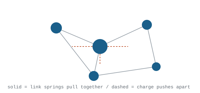
Forces, not coordinates
The layout holds a list of nodes with positions and velocities and a list of forces that alter those velocities on every tick. A repulsive charge pushes every node away from every other node. Links act as springs pulling connected nodes to a target distance. A centring force keeps the whole cloud from drifting off the canvas.
The drawing code does not compute positions at all. It listens for the tick event and copies whatever coordinates the simulation currently holds onto the shapes.
Making it settle
An internal temperature falls a little each tick and scales how far nodes may move. When it drops below a threshold the simulation stops. A layout that never settles usually has forces fighting each other harder than the cooling can damp: charge too strong against a link distance too short.
Charge strength should scale with node count. A value that looks right for thirty nodes will blow three hundred nodes off the canvas, because repulsion accumulates across every pair.
Labels and curved links
Straight links between the same pair of nodes overlap and become one line. Drawing each as an arc with a small radius offset separates them and keeps direction readable. Labels attached directly to nodes inherit their jitter, so binding them to the same tick handler and offsetting along the link angle keeps them legible while the layout moves.
Building one
- Shape the data as a node array and a link array whose entries reference node indices or ids.
- Create the simulation and attach a charge force, a link force and a centring force.
- Append link and node shapes to the drawing surface once, bound to those arrays.
- On every tick, copy the current node coordinates onto the shapes.
- Tune charge strength and link distance together, judging by whether the layout settles rather than by how it looks on the first frame.
simulation.on("tick", function () {
  link.attr("d", curvedPath);
  node.attr("transform", function (d) {
    return "translate(" + d.x + "," + d.y + ")";
  });
});
The tick handler is the whole drawing loop